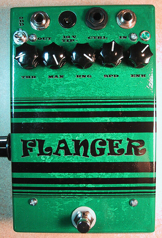
NOTE: All the information on this page refers to SAD1024 versions of the ADA Flanger clone circuit.
Synth
Unfortunately, I will no longer offer PCBs for the SAD1024 version of the ADA Flanger circuit. If you happen to have a SAD1024 chip that you are dying to use in a project, I suggest you find a vintage circuit in need of repair and use your SAD1024 to bring it back to life.


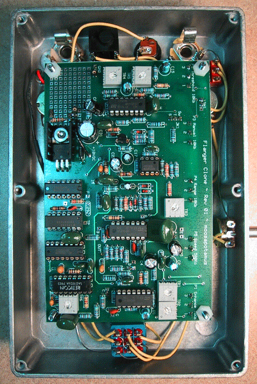
The following information has been created and assembled with the goal of building a circuit based on the A/DA Flanger that uses the SAD1024 BBD chip. The rev.01 PCB layout, below, has been fabricated and verified to work by several members of the DIYstompboxes.com forum. The circuit is exactly the same for rev.02 & rev.3 but the PCB layout was adjusted to incorporate a few minor tweaks/improvements to the PCB layout, mostly shifting placement to allow adequate space for all components.
Building Notes (PCB rev.01 & rev.02)
PCB Layout (rev.02)
Overlay
Top Layer
Bottom Layer
Layout
PCB Layout (rev.01)
Overlay
Calibration and Bench Test Procedure
Bounce Mod Diagram (untested)
(drawn by Stephen Giles)
Additional documentation and background info
Some time ago, the original Rev.3 circuit was adapted by Mike Irwin to replace the out-of-production, obsolete MN3010 with the also out-of-production, but much easier to obtain, SAD1024. His modification was then verified with a very impressive strip-board construction that was built by Stephen Giles.
My revised schematic, above, is a hybrid of the original Rev.3 and Rev.4 versions with Mike’s SAD1024 adaptation. In addition, my layout includes a transformerless regulated (LM7815) power supply and a number of additional pads to make experimenting with the circuit easier, and to allow for easy implementation of a number of alternative modifications (see Building Notes, above).
I collected the following from files that the very cool members of DIYstompboxes.com posted and sent to me over the years (Bill Bergman, Mike Irwin, Stephen Giles, et al, thanks y’all!). This is most of the background documentation that I used to put together the updated clone circuit, above.